Project report
On
“PROCESS AND PERFORMANCE EVALUATION OF NR/POLYBUTADIENE BASED SUB TREAD (BASE) COMPOUND IN HEAVY DUTY COMMERCIAL VEHICLE TYRES”
CONTENTS
I. PREFACE
II. INTRODUCTION
1 What is pneumatic tyre?
2 Historical development
3 Basic tyre performance
4 Classification of tyres
5 Parts of pneumatic tyre
6 Types of tyre
7 Construction
III. SCOPE OF STUDY
IV. METHOD OF APPROACH AND EXPERIMENTS CONDUCTED
V. THEORY
VI. PROJECT AND FORMULATIONS
VII. EXPERIMENT
VIII. RESULT AND DISCUSSIONS
IX. SUMMARY AND CONCLUSIONS
X. FUTURE STUDY PROPOSED
XI. REFERENCE
PREFACE
Quality Productivity and Cost are the three most important keys of survival and success of any modern industry and rubber product is no exception. More often than not, quality and productivity are pitted against each other with conflicting interest. The challenge before a rubber technologist is to strike a balance by making sensible compromises which allows attainment of satisfactory levels on both Quality and Productivity at minimum Cost through the process of optimization.
Quality is the transient phenomenon and its benchmark value is ever on the ascending ladder. The quality of a tyre industry is quantified in terms of its performance, and the ability of a tyre company to give quality tyres is judged by the consistency, with which their tyres meet or exceed the expected performance.
Tyre technology is a vast complex combination of science technology/engineering and art, bringing together a variety of disciplines. The science of tyres involves knowledge in the area of composite structures and geometry. These concepts have been used to derive mathematical models of tyre mechanics.
Tire chemistry and technology of compact materials involves areas of specialty such as tyre reinforcing systems, adhesive theories and applications and rubber and material technology. The properties of these materials and their relationship determine the integrity of the tyre. The construction and composite configuration must be designed to fulfill dynamic tyre performance requirements.
INTRODUCTION
What is a pneumatic tyre?
The Indian Tyre Technical Advisory Committee (ITTAC) defines tyre as an annular toroidal shaped inflatable envelope made of an elastic material, natural or synthetic or a blend there of, reinforced with textile-cord-ply-fabric carcass enclosing bead rings.
· Geometrically it is torus
· Mechanically it is a pressure container
· Chemically it is a material from long chain macromolecules of same or different type of elastomers.
· Structurally it is a composite
Historical Developments and Importance of Pneumatic tyre
Pneumatic tyre is the most versatile and probably the first engineering product made out of polymer and has made it possible the evolution of sophisticated personalized land transportation system. Tyre industry is the world’s second largest industry via, road transport industry employing the largest man power. Without the pneumatic tyre, development of motor vehicle transport would not have been possible. More than 40% of world’s rubber production finds application in pneumatic tyres. Tyre is the most important component of any vehicle and it establishes the only contact between vehicle and the road. The performance of the vehicle is largely dependent on the capability of tyre.
Basic tyre requirements
There are certain basic requirements, which are found to be essentially the same for all type of pneumatic tyres. Even though their relative importance differs with each type, there are some other features:
1) Cushion the vehicle ride:
A pneumatic tyre is the first line of defense against road shocks and its unique property of cushioning provide comfort. Cushioning is imparted by the air and the ability of the tyre membrane to deform radially.
2) To carry the load:
A pneumatic tyre must carry the load when mounted on a rim and inflated to the required pressure. In other words, pneumatic tyre must form an air container of adequate strength disposed in the radial direction to hold the air pressure acting radially.
3) To transmit steering response:
The tyre is required to transmit driving torque and breaking torque efficiently to the ground to put the vehicle in motion. Good tyre to road grip coupled with adequate strength disposed in the circumferential direction underneath the tread of the tyre is required for efficient transporting.
4) Develop adequate cornering force & directional stability:
It is the unique ability of a pneumatic tyre to develop adequate cornering force to counter the centrifugal force or any other lateral forces like wind force, and retain the vehicle on the road while negotiating curves etc. That enabled the development of road transport industry. Excellent grip combined with its ability to undergo lateral deformation helps the pneumatic tyre to develop cornering force. The self-aligning torque, i.e. Product of cornering force and pneumatic trail, is responsible for directional stability. This self-aligning torque brings the tyre to original position and prevents the skidding away when the vehicle is taking a curve.
5) Economic performance:
Every revolution of the tyre leads to periodic strain radially, circumferentially and laterally. This necessitates adequate flex fatigue life for the material and structure and wear resistance for economic service life.
6) Specific tyre requirements
It depends on the particular application
• Directional Stability
• Impact Resistance
• Run Flat Resistance
• Weather Resistance
• Mileage
• Crack Resistance
• Grip in Loose Soil
• Rolling Resistance
• Speed Capabilities
• Puncture Resistance
• Re treadability
• Low Cost
• Floatation
The pneumatic tyre carries the vertical load and deforms vertically to cushion the ride i.e., X-direction transmits the traction and breaking force and the Y-direction get the vehicle in motion and develop cornering force. And it transmits steering torque in the lateral direction for vehicle control i.e., in Z- direction. It has to perform in all the 3 directions simultaneously and efficiently without compromising each other. So the tyre is the only engineering product so far developed has a 3 directional heavy-duty performance capability.
Classification of tyres:
Tyres can be classified according to their construction, application and the nature of air container. They are:
I) Based on construction:
a) Bias tyre:
A bias tyre has a carcass which is made up of fabric cords as the reinforcement crossed over each other at an angle of 35-40 to the tread centre line. The number of such crossed layer called plies is a function tire’s load carrying capacity and related to the inflation pressure. The diameter of the individual ply depends upon the yield strength of the cord material and ultimate strength demand of the tires. The layers of crossed cords in the carcass of this tyre form a strong and interlocking net to resist the impact and load. This may or may not be included with breaker reinforcement between carcass plies and tread to improve directional stability. A bias construction is continuous in its carcass structure from bead to bead.
b) Radial tyres
A radial tyre consists of a radial carcass and a stabilizing belt underneath the tread. Radial carcass consists of reinforcement layer of fabric cords running from one bead to another at 90° to the tread centerline and is designed to hold the air pressure. The stabilizing belt consist of reinforcement layer of high modulus fabric cords running circumferentially around the carcass at an angle of 18-22° to the tread centerline beneath the tread and designed to transmit driving, breaking and cornering torque. The function of tread and the side wall are separated to a great extent such that major short comings of bias construction are eliminated. This construction requires greater number of components than bias tyre and very precise placement of component is necessary.
c) Bias belted tyres
This design combines a bias construction carcass with multiple ply cord belt. The resultant tyre retains much of the road stability of the conventional tyre and also provides considerably increased mileage by reduction of squirm against the road surface. This tyre can be handled throughout manufacturing on existing equipment built for the production of bias tyre.
II) Tube type & tubeless type
Tube type tire which are popular in India contains a separate air inflatable inner tube for the purpose of inflating the tire. In tubeless tyre the tube is absent and the function of the tube is performed by a layer of halo butyl rubber. The rim profile has to be changed to get a perfect seal between the rim and tyre. The comprehensive seal between the tyre bead and the rim is obtained by the incorporation of a compressive fit of rubber layer underneath the strengthened bead wire coil which force the profiled bead up an annular seat inclined at between 50 and 150 on the rim.
Components of tyre:
Tyre is made of a large number of components, which are being assembled during tyre manufacturing. Each component has its own functions in the performance of tyre. The main components of a tyre and their functions are briefly explained below.
1) Drum squeegee
Drum squeegee is applied as the innermost layer of the plies above the drum. It protects the tube from the ply cord and also protects the carcass from moisture. They are made of very high green strength compound. In tubeless tyres they have the function of maintaining air inside portion between rim and tyre. So they should have very good air impermeability also
2) Plies
Carcass plies that gives the tyre strength to hold the air inside it. The plies can be considered as a skeleton for rubber exterior. Each ply consists of a layer of tire cord with a carefully chosen diameter, processed to a closely controlled number of cords per inch, coated precisely with rubber so that each cord is completely insulated by rubber from its neighbors, and cut crosswise at a very precise angle. Each ply is laid into a building drum at an exact angle in relation to the drum axis and other plies. In the case of a bias tyre, the cords are arranged at an angel of 35-40 and radial it is 88-90. The behavior of the plies under the stress and under other imposed forces such as vehicle load, determines the final property of the tyre. At the same time, the casing has to be capable of enduring deformation radially, laterally and circumferentially in order to accommodate forces involved in rolling, bouncing, steering, cornering and breaking. There are two types of plies used in carcass inner ply and outer plies. The EPI of outer will be less than that of inner ply to obtain a gradual reduction in modulus from inner surface to the tread area. The fabric is dipped with an adhesive before calendaring and is skim coated with rubber for getting a total thickness 1.00- 1.30 mm by using a calender. Nowadays steel wires also are used as the ply material.
3) Ply squeegee & gum strip
The coating of rubber on plies is to absorb shear strain between the plies and to prevent the internal abrasion between the cords. More over the increasing in diameter from green tyre to cured tyre will results in high stretch at the centre. This will necessitate higher rubber gauge at the centre. The thickness of the outer ply squeegee and breaker should be high. This is to compensate for high lift at the centre portion of the tyre and to absorb the higher shear strain on the outer layer during the curing process. The squeegee is applied at the centre portion of the ply. In the heavy duty tires, turned up plies ends in squeegee. It may cause concentrated shear and flex or hinging in the junction with resultant rapid and localized heat build up. So, care must be taken to make these stocks completely compatible with surrounding components.
4) Breaker
The purpose of breaker is to raise the modulus of the tread area, thereby maintaining the inflated tyre tread profile and reducing the tread pattern movement as it contact with road. In a bias tyre construction, rubberized textile identical to that of plies is used as breaker. The angle of breaker cords is about 45° with the axis of the tyre. EPI of the breaker is always less than that of inner and outer plies. Two strips are slightly off set to achieve a graduated step down of stresses at the edges to minimize the stress concentration.
The breaker is a blanket of one or more layers of cord or wire and rubber built in to the tyre between the outer ply and the tread. Generally it covers laterally the width of the tread contact on the road and serves to absorb and distribute impact shocks over a broad area of carcass plies and reduces punctures and ply breaks.
5) Chafer
The chafer is a narrow circumferential strip of material which encloses the bead area. It starts slightly above the rim flange height and extend downwards and round the bead base. It provides some protection from the rim chafing to the carcass. The component is made up of square woven fabric, which is skim coated with rubber and cut at an angle of 45°. In the case of tubeless tires, it serves to prevent air leakage through the bead area. In this the chafer should be an asymmetrically coated fabric. In some of heavy truck tires multiple layers are required to provide adequate protection. Another important function of chafer is to prevent the damages by the tools used for mounting and demounting of tires.
6) Bead
Bead consists of fairly stiff hoop of strong wire embedded in rubber serving to prevent the tyre from stretching and leaving the wheel rim and also an anchorage to the layer of carcass cords. Bead enables the transmission of traction and braking force between rim flange and tyre. The bead bundle is constructed by winding a flat tape containing several numbers of bronze coated steel wires with a predetermined number of turns to achieve the desired strength. The number of beads and number of turns and stands are decided based on the bead safety factor. The bead wires are coated with a rubber compound by means of a T- head extruder. The compound is always a fast curing compound with a very high modulus to match with steel. It has a very good adhesion property.
7) Bead apex
A triangular shaped continuous rubber profile is applied the top face of the bead is called bead apex. The main purpose of this component is to fill the gap above the bead bundle during the ply turn up; it also helps the smooth build up of tension from bead bundle to the tyre carcass during the service by providing a steady gradation of thickness.
8) Bead flipper
Bead flipper used to pack the filled bead. By flipping, a good consolidation is achieved between bead bundle and filler so as to prevent the movement of bead unit at the time of bead stitching. It also gives good adhesion between the carcass and bead. This flipper is made with a bias cut fabric.
9) Tread
Tread is the wearing surface of the tyre. In cross section, it is substantially rectangular across the centre portion and tapering down to the very fine edges. The thickness must be calculated to accommodate the pattern fragmentation in the tyre mould and to allow an adequate residual thickness beneath the pattern groove. The tread region extends to a position slightly above the maximum flux zone in the upper sidewall region. The main properties of the tread are abrasion resistance and heat build up which are contradictory to each other. So in truck tyre, tread are extruded as two components – cap with high abrasion resistance and base with low heat build up. A thin layer of cushion compound is adhered to its bottom for getting good tackiness. The treads are provided with some patterns to improve the traction and driving comfort. They are three types of patterns; rib, lug & semi lug. Rib design is oriented in circumferential direction and possesses characteristics to provide good service for all wheel position. It is best for lateral traction. Hence it is used in front tires. The lug pattern which is best for forward traction is used in rear tires. Semi lug is a combination of both; it is designed for the application in poor road condition such as muddy roads
.
10) Side wall
Side wall is an extruded rubber component which serves to protect carcass structure from weathering and chafing damage together with tread which overlap in the buttress region to form the outer most layer of the tyre. It controls the ride and supports the tyre. The gauge of the sidewall is an important factor determining the heat build up. In buttress region heat developed is more. Shoulder region provided with deep radial groove for cooling. All the tyre information’s are carried on the side wall region.
AN OVERVIEW OF TYRE SERVICE FAILURES
During the service life of a tyre, it undergoes millions of cyclic flexing under varied service conditions like, over loading, over/under inflation pressures, hilly and uneven terrains and at very high speeds. Customers because of the increased operating cost, which is largely contributed by fuel and tyre prices, dictate always an increased performance level from tyres. The immediate consequence of this ‘cost in balance’ is an increased abuse of tyre. This is by way of over loading or high speeds or even inadequate mechanical maintenance of vehicle. The net effect of all these negative factors is higher rate of tyre failures.
The tyre failures can be broadly classified as due to:
1) Design related
2) Manufacturing related and
3) Tyre service related.
The three major failures, contribute for almost 80 % of tyre failures, they are;
a) Tread shoulder separation
b) Turn up separation
c) Bead failure
a) Tread shoulder separation
The major reasons for this failure are over or under inflation, over loads and high speeds over bad roads, etc. This can aggravate when there is an anomaly from assembling tyre in the form of excess splice, higher rubber mass or even an incipient air trapped during splicing of treads during tyre assembling. It results in rubber getting overheated and cord at shoulder area looses their stiffness properties and breaking away from tread shoulder.
b) Turn up separation
It is a separation or failures at the ply turn up ends. This failure is often reported from the markets where tyres are exposed to higher pay loads over and above the recommended levels. The distribution of tyre cord loads in this region is very important. The cord force pattern and peak-peak forces in a deformation cycle are greatly influenced by the method of construction and the turn up heights followed for each construction. The cyclic energy dissipation, tyre pressures distribution in the foot print area, etc. affect the cord-load distribution in the turn up region and non-uniformities will direct towards excessive inter laminar shear strain between the turn ups. More over the increased temperature causes the cord-rubber linkages to break and thus turn up failures occur.
c) Bead failure
When tyre is designed with adequate bead strength, a failure at bead area or damage of bead in tyre service is mostly due to wrong application or improper care of tyres. This defect is normally occurring in the heavy overload application and some time related to fitting of tyre on rims or poor mechanical condition of rims.
SCOPE OF STUDY
The main objective of the work was to design a NR/Poly Butadiene blend sub tread (base) compound for truck tyre application and validate the same in the tyre manufacturing process, including its indoor endurance evaluation in truck tyres by testing on a testing wheel. The challenging part of the work is meeting (or exceeding) the present level of performance, without compromising the overall durability of the tyre.
The sub tread or the tread base is the component of the tyre that lies just between the tread cap and the cushion. Its function is mainly to absorb heat, from the cap tread compound and the carcass composite that is generated during the running of the tyre. The most desirable properties of the tread base are:
- Low heat build up (low hysterisis)
- Flex crack resistance
- Maximum heat stability (minimum degradation)
- Low cut growth.
Reason for the study:
Natural rubber is the most balanced general purpose rubber for such performance requirements, because Natural rubber has a very low heat build up property, and also meets the other specified needs of a tread base compound with appropriate compounding.
Due to the increased demand of Natural rubber (largely due to increased production of truck radial globally and higher percentage of Natural rubber used there of) there is a large gap between demand and supply. Due to its scarcity, industries are forced to explore more flexible and compatible technology utilizing total available rubber including other general purpose synthetic rubbers. The two obvious synthetic rubber choices are Polybutadiene rubber and Styrene butadiene rubber. Polybutadiene rubber is selected for this study as it has the following desirable properties:
· Good abrasion resistance
· Low heat build up
· Good heat and weather resistance.
· Compounding flexibility/scope
When sufficient quantity of Poly Butadiene is made available, a NR/Poly Butadiene blend in truck tyre sub tread, against conventional 100% NR based compound can substantially reduce total NR consumption in tyres. This would help conserving costly and scarce Natural Rubber partially and solve the problems of tyre industry to some extent, hence this study.
THE CHALLENGE:
Among the commercial vehicle tyres manufactured and sold in India, truck tyres are of higher demand an importance. This is because these tyres are subjected to severe running conditions. These heavy duty tyres are therefore worn out more quickly and therefore reducing the tyre mileage.
Another reason for tyre failure is the loading conditions in India. In India a truck tyre is loaded with a loading condition which is more than what a tyre can withstand. Here the trucks are load to such extend to decrease the transportation cost which eventually lead to severe tyre failure. Therefore the compound developed in the study should also have good dynamic load bearing capability.
The study therefore needs to focus on service conditions of tyre and design a suitable formulation, which can render better,
- Tear resistance
- Cut growth resistance
- Tensile properties
- Modulus
- Elongation and
- Low heat build up properties.
Besides with above desirable properties, developed compound should have rate of vulcanization (cure rate) matching to the established cure cycles of tyres.
The positive result of the study will be a boon to the customers and the industry.
METHOD OF APPROACH
v Eight formulations are tentatively fixed.
v Four formulations are selected initially for optimisation of cure system, along with matching physical properties.
v Cure system is optimised along with matching physical properties.
v Optimised cure system is employed in all eight formulations.
v Full evaluation of all eight formulations is done after compounding and mixing is done in shop floor Banbury mixer.
v Based on the evaluation results, two compounds are selected for tyre making.
v The selected two compounds are used for tread extrusion and tyres are made
v The build tyres are cured and given for indoor tyre testing and for further field evaluation.
EXPERIMENTS CONDUCTED
v Un aged physical testing.
· Tensile testing.
· Tear testing.
v Aged physical testing.
· Tensile testing.
· Tear testing.
v Demattia cut growth test.
v Dynamic Mechanical Analysis.
v Heat build up analysis.
v Rebound resilience.
v Crosslink density.
v Dispersion.
THEORY
Tread is the part of the tyre that comes in contact with the road, the tread should have the following properties
Ø Good abrasion resistance
Ø Good traction
Ø Good steer ability and
Ø Low rolling resistance.
The tread consists of three different parts viz,
Ø The Cap portion
Ø The base or the sub tread and
Ø The cushion.
The cap portion is the part which comes in contact with the road surface, its main function is to provide good traction and also good abrasion resistance.
The base or the sub tread is to provide a cooler running, basically it acts a coolant. Heat generated from the cap is hindered by the base to flow to the carcass area. The heat is generated both from the outer cap region and also from the inner carcass area, during the service of a tyre. This heat if accumulated can lead to defects like:
Ø Tread shoulder separation
Ø Circumferential cracking at shoulder buttress area.
The base is a critical component in curing also. The base occupies the thickest part of the tyre structure, extending from the shoulder to the inner ply region. Since the base is situated in the innermost part of the tyre structure, curing of this part is very critical.
The heat supplied from both the outer dome jacket as well as the bladder (in curing press) must be sufficient enough to cure the base. So when the base is cured it can be assumed that the tyre is cured. So the cure cycle of a tyre is designed in such a way that the base is cured at least 15-25% of optimum cure when tyre is removed from vulcanizing press (ensuring that it is exceed the ‘blow point’). So in a way we can say that once the base is cured, the other part of tyre is also cured.
The base compound must have good heat stability also. It should be able to withstand high temperatures without degradation. The cure system is designed in such a way so as to avoid reversion and to maintain a plateau type rheo curve. Large amounts of antioxidants are needed to avoid degradation due to heating of the base and to improve heat stability. Over heating of the base compound can result in separation at tread shoulder area there by leading to premature tyre failures.
The cushion compound is made purely of Natural rubber; its function is to provide a cushioning effect and to give a good adhesion between the tread and the carcass. The cushion is usually a thin layer of rubber compound stitched to the bottom of the tread by stitcher rolls during tread extrusion.
PROJECT AND FORMULATIONS
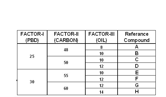
The compounds are designed with different levels of Polybutadiene, Carbon and process oil loadings. There are two base levels of Polybutadiene loadings, four levels of carbon loadings and four levels of process oil loadings as shown below.
Based on this, eight formulations are evolved and are evaluated, namely A, B, C, D, E, F, G, and H along with a control compound (R).
The cure system of the above eight formulations are to be optimised, in the formulation. Since TC 15 (15 % cure time) values for each compounds is critical with respect to vulcanization new formulation to be fine tuned to meet this value in order to run in the same cure cycle. TC 15 is defined as the minimum cure time required restricting the rubber flow inside the mould cavity. It is also called the blow point. It is also defined as the time to obtain 15% of the maximum torque value in the rheo curve. For this, four formulations are selected first, viz A, D, E and H along with the control compound R. So the initial step is to prepare the master batch for these five compounds.
Mixing:
The mixing of the master batch is carried out in F270 Banbury with fill factor 0.75, following the standard mixing conditions and mixing sequence.
The master batches are mixed in the shop floor Banburry. The batches are then mixed for final batch in the laboratory banburry. The cure system is optimized by trying different accelerator dosages. First higher dosages of TBBS are tried but the results are not comparable, so the accelerator system is changed to CBS system. In CBS system different dosages are tried and 1.2 phr CBS is fixed along with 0.2 phr DPG.
After the cure is optimized all eight formulations are made in bulk quantity in shop floor banburry. The master batches are compounded under the standard conditions and mixing sequence. After master batch mixing, final batch is mixed.
MIXING PARAMETERS FOR MASTER BATCH AND FINAL BATCH:
After the finalization of all eight compounds, samples are given for regular rheo study. The rheo is done in ODR at 1420C for 60 minutes.
FULL EVALUATION
TESTS CONDUCTED:
The following tests are decided to be conducted on all the eight samples along with the control compound.
· Physical tests
a) Un aged
b) Aged
- Dynamic mechanical analysis
- De mattia cut growth
- Heat build up
- Rebound resilience
- Dispersion
- Crosslink density.
VALIDATION OF COMPOUNDS IN THE PROCESS:
Extrusion:
Treads for both the selected compounds A and D are extruded maintaining the standard conditions and parameters with an 8 ½ X 10” extruder. Two sets of treads for lug pattern and rib patterns of 10-20 tyres are extruded. The treads are extruded without any problems or defects and are loaded on to leaf truck. The leaf trucks were then held up for a minimum of 4 hours for maturation before green tyre assembling.
Tyre building:
Tyres of 10.00-20 sizes for Rib and Lug patterns are build using these treads under standard process conditions. There are no significant problems during the assembling of the green tyres. The green tyres are then kept in GT trolleys for maturation, before curing.
Tyre curing:
The assembled Rib and Lug green tyres are cured. Curing of the assembled tyres is done using the standard curing presses, using conventional cure cycle. The conventional curing cycle employed the using of high pressure steam, hot water and cold water. After curing the tyres are given for Post Cure Inflation (PCI).
Tyre testing:
The cured tyres are then given for load endurance testing. The testing is done by applying step loads under standard conditions along with a control 10.00-20 size tyre. Different step loads are given at different intervals of time. The tyre is subjected to a 101% load first for 48 hours, if the tyre survives then it is again run for another 4 hours under the same loading. At this point temperature readings are taken from the shoulder as well as from the centre line of the tyre. The process is then repeated for 110, 120, 130, 140, 150, 160, 170, 180% loadings etc for four hours duration for each load step, and their respective temperature readings are taken until tyre failure.
EXPERIMENTS
Specific gravity
Specific gravity test is used for checking the purity of the compound. Using zinc chloride solution carries out this test. The loss of ingredients during processing can be found out by this test
Dispersion
Dispergrader 1000NT model manufactured by optigrade, Sweden was used for this study. The test was done in accordance with 100X magnification. The degree of carbon black dispersion in a rubber compound is important because certain physical properties, e.g. tensile strength, hystersis and abrasion resistances are influenced by dispersion. Normally a rating of 1 to 6 is classified as doubtful .A rating
of 10 indicates a rate of dispersion properties. There are two types of magnification. Here 100X magnification is used.
100X magnification
In this method there are two values, x and y. This method is based on ASTM D 2668-88
The x values determines the destitution of filler in the compound .The X values is based on an image comparison with a set 10 references pictures of Phillip’s. Best dispersion will give the maximum value for X and worst dispersion will give minimum value for X
The Y value is based on size and number of surface irregularities. It gives an idea of the agglomerates size in the compound. A high value of Y means the agglomerates size is very law.
Rheometer properties
a) Monsanto oscillating disc Rheometer(ODR2000)
The equipment sued for the test was the ODR2000 of alpha technologies. The cure characteristics of the compounds were determined using ODR2000 as per the ASTM D-2084.The cure rate; state of cure and processing characteristics can be understood from this test. Here the sample was subjected to constant amplitude of shearing as it occurs. The oscillating rotors occurs that was embedded in the sample confined to the die cavity under pressure and controlled temperature of 141.7°c for 45 mins the parameters obtained from the rheograph are given below:
1. Minimum torque (ML): It is the measure of the stock at the test temperature.
2. Maximum torque (MH): It is the measure of stiffness or modulus at the test temperature. It is also an effective measure of charges in tensile modulus and cross link density
3. Induction time (Ts2): At normal Rheometer temperature, the induction time is a measure of the available for mould flow. It is also the measure of the time available for mould flow. It is the measure of process ability similar to moony scorch
4. Optimum cure time (T90): It corresponds to the achievement of 90% of maximum cure. It is calculated as, time for 90% maximum cure,
Tc90 = (ML-MH)*0.9+ML
5. Cure rate index: Cure rate index corresponds to the rate of cure. It is calculated from the index corresponds to the rate of cure. It is calculated from the Ts2 and T90 values. Cure rate index =100/T90-TS2
B) Monsanto moving die Rheometer (MDR2000)
It also measures the cure characteristics of the compound as ASTM D-5289-95 .It differs from ODR2000 in the following respect. In MDR 2000 there is no separate disc; instead of the lower half of the die correlates the upper die correlates with the degree of vulcanization as function of cure time .The parameters measured from the Rheograph are
1 Minimum torque
2 Maximum torque
3 Induction time
4 Optimum cure
5 Tan delta
Tan delta
It is the ratio of loss modulus to storage modulus. Loss modulus s the measure of viscous component while storage modulus is the measure of resistance to deformation (elastic component)
Tan delta = loss modulus / storage modulus.
The heat build up due to hysteresis depends on the loss modulus and hence tan delta value is a measure of heat build up also.
In MDR, two types of tests were done:
1) Rapid MDR:
In this test, the sample was undergoing a temperature of 191°c for 4 mins. This test Is Used for fast releasing of the compound.
2) Regular MDR
In this test, the sample was under going a temperature of 141.7° c for 45 mins.
This more accurate than rapid MDR
Mooney properties:
The Mooney test, which is used as a routine test to assess, the processability of raw stock and compounds, was carried out for all the compounds in accordance with ASDM D1641-81. The equipment used was Monsanto co USA makes model MV 2000. Here a rotating disc in a shallow cylindrical cavity shears the samples as it cures.
The rotor speed is 2 rpm. The surface of the disc and of dies, which form the cavity, are serrated in a grid Patten to grip the rubber mechanically. The optimum test specimen consists of two pieces, which fill the cavity completely: one sample is placed above the rotor and the other beneath it .The torque required to move the rotor is measured, which gives the measure of viscosity of the compound.
The Mooney viscosity of the compound is expressed as ML (1+1.5)@135° c. The test conditions are as follows:
Temperature of the die cavity 135°c
Rotor size large
Pre heating time 1 min
Set time 1.5min
Total test time 2.5 min
Mooney scorch
Mooney scorch test is done in accordance with ASTM D1646. The scorch time gives the measure of processing safety. It also contributes to the stress relaxation study and elastic behavior of the polymers the scorch times T5, T10 and T35 are obtained.
Physical test:
Molding
The final compound were aged for 24 hours before molding .The compounds were sheeted out to the required thickness using laboratory mill molding for tensile and tear properties were done in a 22”X 24” steam heated automatic process.
The sample for testing except anaerobic aged were molded at a temperature of 141.7° c for 45 mins at 112KG/Sq.cm².In the case of anaerobic aged samples the time given was 90 minutes, all other parameters were the same. The molded pieces were cooled in water and conditioned at 23±2 c and 50% relative humidity for 24 hours before testing.
Ageing
A cellular type-ageing oven was used for ageing the samples. This was done as per the IS: 3400, samples were exposed to 100° c for 48 hours. After the removal from the oven the samples were conditioned at 23±6° c and 50%RH for 24 hours and various properties were tested.
Percentage retention after ageing = (property before ageing – property after ageing) /property before ageing.
Tensile stress-strain properties
Instron universal tester model 4302 was used for the study .the stress strain values were measured as per the ASDM D 412. Dumb bell shaped samples were stumped from cured sheet parallel to the grain direction using dumbbell shaped die (C type) The crosshead speed was 500mm/min .The thickness of the specimen was measured and feed to the computer –aided machine so that the following parameters were recorded.
a) Tensile strength:a) Tensile strength
Tensile strength is defined as force per unit area of original cross sectional. area required for rupturing the sample
.Tensile strength = (load at break) / initial cross sectional area. psi
b) Modulus:
Modulus is the stress at particular strain. It is calculated as follows,
100%modulus (psi) = (load at 100% elongation) /initial cross sectional area
200%modulus (psi) = (load at 200% elongation) /initial cross sectional area
300%modulus (psi) = (load at 300% elongation) /initial cross sectional area
Elongation was measured the ability of the rubber to stretch without breaking. elongation at break is calculated as
Elongation at break = (length at break –initial length) x100/initial length.
Tear Strength:
Tear strength is calculated as per the ASTM D –624 with un necked 90 angular specimen using Instron tester 4302:Germany.astm die c was used for cutting samples. The cross sectional speed was 500mm/minute .the result is expressed in Lb/in. The gauge of the specimen were measured and fed to the instrument.
Hardness
Hardness is the modulus at low strain. Hardness of the valcanisate was measured with the help of Shore A Durometer as per ASTM D-2240. The instrument consists if a calibrated spring to provide the indenting force. The load imposed by the spring varies with the indentation. Reading was taken after 10 seconds after indentation. When the firm conduct had been established with the specimen and the mean value of the measurement is reported.
Heat build up
Heat build up is measured by subjecting the standard sample to flexing in a Goodrich Flexometer in accordance with ASTM D 623. A specified load is applied to the test specimen which is mounted between the anvils, through a lever system having high inertia. An additional high frequency cyclic compression of specified amplitude is imposed on the test piece (1800Hz). Due to flexing heat is generated and this increase in temperature is measured at a specified time with the help of thermocouples. The change in the height of the test piece provides a measure of the compression set. A test piece may be subjected to more severe fatigue which condition to affect a blow out if the test piece.
DeMattia cut growth:
DeMattia cut growth measurement involves giving a 2mm hole in the notch of the standard specimen the testing is done in accordance with ASTM D 813. The demattia sample is moulded at 141.7°C for 60 minutes. The moulded sample is left for conditioning. After the conditioning of the sample a small hole of 2mm thickness is given. The sample is then subjected to 180° bending. The cut growth for specified cycles is noted at regular intervals. The lesser the growth the better the compound will survive
Cross linking Density:
Each cured samples are cut into small pieces of about 0.2 - 0.3 grams in three different shapes, their initial weights are noted. These cut samples are then allowed to swell in toluene solution for about 48 hours. After swelling the samples are carefully wiped with tissue paper to remove excess toluene from its surface. These samples are then weighed carefully and their respective swollen weights are noted. These samples are then kept in drying oven maintained at 70°C for 24 hours. After drying the samples are taken and weighed again carefully and their de-swollen weights are noted. These noted weights were then substituted in a mathematical expression to calculate the crosslink density.
Rebound resilience:
Samples were prepared at 141.7°C for 60 minutes, and kept for conditioning for 12 hours. The testing is done according to the ASTM standards ASTM D 1054. After conditioning samples were tested for rebound resilience at 100°C and room temperature using a pendulum type Zwick rebound tester. The samples were conditioned for about 30 minutes in an oven at 100°C before testing. The rebound resilience was calculated by taking the average values of the three rebounds in terms of percentage.
SUMMARY AND CONCLUSIONS
SUMMARY
COMPOUND PROPERTIES
The eight experimental sub tread formulations are identified as A to H and control compound as R.
For compound A the rheo properties like TC15 values, mooney properties and the physical properties like EB tear and tensile strength are comparable with control compound. The dispersion is good and it has better cut growth resistance properties. The cross link density is good and comparable results are obtained in the case of Heat build up.
Compound B however is marginally inferior to compound A. Compound B have good rheo results and modulus values, but the elongations at break values are lower than expected. It shows good dispersion and crosslink density but the tear strength is lower than expected. The heat build up values and rebound values are not matching too.
Compound C gives good rheo properties, dispersion, cross link density, rebound resilience and its cut growth properties are good. The elongation at break is good and comparable. The HBU properties are not good; it has low modulus but has good results for crosslink densities.
Compound D is the best compound among the eight compounds and gives good results for Rheo TC15 values, tensile tear, Elongation, modulus and heat build up. The tan delta values are good and have good crosslink density. The rebound resilience is good and comparable.
Compound E shows good dispersion but it is having low values of TC15, modulus is high, with low elongation. Demattia cut growth has poor results. HBU is higher, rebound resilience is not good.
Compound F has good rheo properties, it shows good dispersion and cross linking. It has high modulus and the EB values are low. Cut growth is comparable. HBU is very high; re bound is lesser than compound D.
Compound G has good rheo results, cross link density and good dispersion. It has high modulus with lower elongation, cut growth is very poor. HBU is high and not comparable. The rebound resilience is also poor.
Compound H has poor rheo values, has good modulus with low elongation properties. Tear strength is high and good. Demattia results are poor, dynamic properties are also not comparable and are poor. The rebound properties are good and closer to the control compound.
Out of these eight compounds, based on overall evaluation results two candidates are selected. The selected compound candidates are A & D. These compounds were taken for further processing including tyre making.
CONCLUSIONS
The blending of Natural Rubber with a synthetic rubber is not an easy task, especially while concerning proper blending and mixing of the two. This is because; the physical and the chemical properties of the natural and synthetic do not match with each other thus providing improper mixing and undesirable properties. In the case of blending Natural rubber with Polybutadiene care had to be taken over all these aspects. The use of Polybutadiene in a way has served to replace the Natural Rubber. The replacement of Natural Rubber with synthetic rubbers had to be concentrated mainly because of two reasons; they are (I) the scarcity of Natural rubber and (II) the increase in the cost of the Natural Rubber.
In the project two levels of Polybutadiene was blended with Natural rubber. The first level was 25 phr and the second level was 30 phr PBD respectively. The 25phr PBD loading had no much effect on the processability of the compound. It showed no much variation in the physical test results i.e. tensile, tear, elongation etc.
Based on satisfactory processing and properties obtained with 25 parts Poly butadiene in compound ‘A’ and ‘D’ these formulations are suggested for bulk evaluation in tyres.
The use of 30 phr PBD in the base compound did not have satisfactory results, therefore not recommended for further evaluation. The inference obtained is that any further increase from 25 phr base level loading of Poly butadiene would be inappropriate for base compound.
By
TG Vishnu Sharma
TG Vinayaka Sharma